This DIY electronic Kit based on Roman Black circuit and hex file for
PIC16F628A. With our DIY kit you can assemble capacitance meter for
your home lab. This capacitor meter can measure discharged capacitors
from any type: ceramic, mylar, metal film or electrolytic. It very
performance device for reasonable price, suitable for people who like
DIY electronic projects. The cap meter has several advantages:
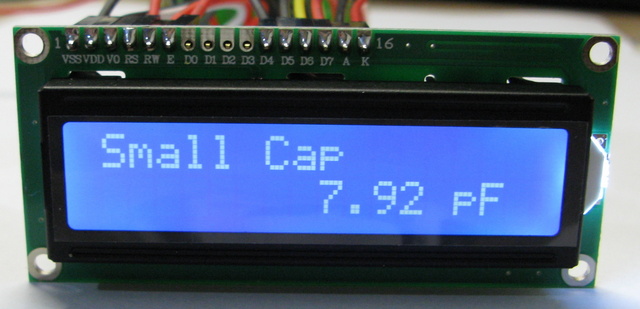
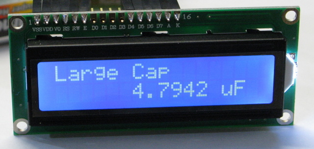
Technical specifications:1. Very high resolution measure: from 6 to 7 digits.
2. Wide measure range: It can measure capacitors from 0.01pF up to 50uF
3. Easy to assemble and have technical support
4. Do not need hardware calibration with external capacitors
5. Accuracy 1% or better
6. Auto zeroing, floating zero and negative capacitance (relative to zero).
7. Have simple one-button interface: press zero button after powers up
and connect the capacitor you want to measure.
8. Can be powered from one 9V battery or stabilized DC power supply 8-12V
The meter can display negative capacitance values compared to the zero
point. So if you zero it on a
good 1nF cap, other 1nF caps tested will read as + and - the
difference, so it can be used to check cap
error against a known good cap.
The second advanced feature is the auto calibrate mode. If the button
is held for 2 seconds the cap
meter enables auto zero calibration. Then any time when there is no
test cap connected (<3pF on test
leads) the cap meter will slowly "trim" its zero calibration by about
0.01pF every second so that it is
always correctly at zero! When in auto-calibration mode it can still
be zeroed by pressing the button.
We created two versions of this product: Beginner and Advanced edition.
The Beginner Edition has very smooth assembling process, so even if
you just start with electronic hobby you can easy solder it. It have
LCD installation with 12 dupont wires and can be mounted to almost any
suitable project box. We tried to make the price of the product as
low as possible, so that it is accessible to anyone engaged in
electronics. Also you can buy this version of the kit without LCD if
you want to use your own. The kit is available from:
http://radiohobbystore.com/diy-kits/high-resolution-capacitance-meter-diy-beginner-lcd.html
The Advanced Edition has a more complicated assembly process. LCD is
installed on four hex standoffs over the pcb. It have onboard zero
button and also you can connect external zero button. We also add
protection diode to prevent wrong +- power supply connection. This
version is more compact, but requires some experience in the assembly
and soldering of electronic devices. The kit is available from:
http://radiohobbystore.com/diy-kits/high-resolution-capacitor-meter-diy-pro.html
To improve the accuracy and stability of the measure process we use in
our project 1% 10K oscillator resistor and temperature stable 270pF
NP0, so there is almost no temperature drift. Otherwise, if you
connect test leads with crocodile clips to terminal block out, it's
normal to see small capacitance drifts because the capacitance between
the leads!
Technical support for the kit can be given on multi-language: english,
russian or hebrew. Respond time for your request can vary, but usually
during 24-36 hours you'll receive the answer.
BUY NOWhttp://radiohobbystore.com/diy-kits/high-resolution-capacitance-meter-diy-beginner-lcd.html
Package include:1x Manufactured high quality PCB
1x Trimmer Potentiometer 20K
4x 1% Metal Film Resistor 1K5
1x 1% Metal Film Resistor 10K
1x 1% Metal Film Resistor 120R
3x Multilayer Ceramic Capacitor 100n 50V (104)
2x Ceramic Capacitor 22p 50V (22)
1x Ceramic Capacitor NP0 270p 50V (271)
1x Electrolytic Capacitor 1000uF 16V
1x Electrolytic Capacitor 100uF 10V
1x PIC16F628A programmed with hex
1x LM7805 5V Voltage Regulator
1x LCD 16x2 HD44780 compatible
1x 16.0000 MHz Crystal
1x DIP Socket 18 Pin
1x 2.54 mm Single Row Pin 40Pins
1x Jumper 2.54 mm
1x Push Button Panel Mount SPST-NO
12x Dupont Wire 1P-1P for LCD connection
1x Ribbon Cable Wire 20cm for other Connection
1x Terminal Block PCB Mount 2 position 5 mm
1x 9V Battery Clip
PDF file with step by step assembling instruction will be deliveried to your e-mail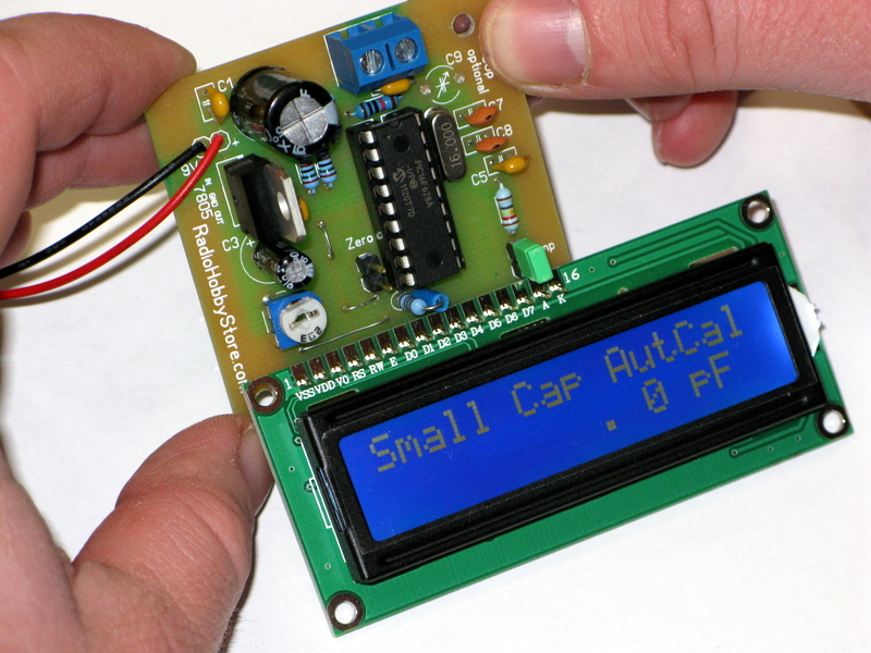 The Circuit and HEX File was developed by Roman Black